
(a) State two essential differences between a moving coil galvanometer and a d.c. generator.
(b) Explain the term eddy currents and state two devices in which the currents are applied.
(c) State the principle on which the potentiometer is based when it is functioning.
(d) A source of e.m.f. 110 V and frequency 60Hz is connected to a resistor, an inductor and a capacitor in series. When the current in the capacitor is 2A, the potential differences across the resistor is 80 V and that across the inductor is 40 V. Draw the vector diagram of the potential differences across the inductor, the capacitor and the resistor.
Calculate the:
(i) potential difference across the capacitor;
(ii) capacitance of the capacitor;
(iii) inductance of the inductor. [π = 3.14]
Explanation
a) Differences between a d. c. generator and a moving coil galvanometer.
| D. C. generator | moving coil galvanometer |
| converts mechanical energy to electrical energy | converts electrical energy to mechanical energy. |
| uses split rings or commutator | uses hair springs. |
| rotation of coil is continuous | rotation of coil is incomplete |
| uses carbon brushes (as terminals) | uses jeweled bearings (as terminals) |
(b) Eddy currents are currents induced in a conductor when subjected to varying magnetic field.
Any valid additional information e.g.
- eddy current flows in a circular path or closed loops;
- eddy current generates heat;
- eddy current cannot flow through gaps or slots;
- The currents move in such a direction as to oppose the change producing them.
Devices in which eddy currents are applied
- pointers of sensitive electric meters
- sensitive mass balances
- brakes in large electric motors
- speedometers in automobiles
- detection of cracks in railway tracks
- detection of metals
(c) Principle on which a potentiometer is based
When a steady current is allowed to pass through a uniform wire, equal lengths of the wire will have equal potential differences.
OR
The p.d across a length of a wire is (directly) proportional to the length provided the wire has a uniform cross section.
(d)
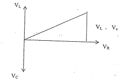
Vector diagram showing
V\(_L\) with arrow
V\(_C\) with arrow
V\(_R\) with arrow
(i) V\(^2\) = V\(_R^2\) + (V\(_L\) - V\(_C\))\(^2\)
110\(^2\) = 80\(^2\) + (40 – V\(_C\))\(^2\)
(40 – V\(_C\)) = \(\sqrt{(110 + 80) (110 – 80)}\)
40 – V\(_C\) = + 75.5
V\(_C\) = 40 + 75.5
V\(_C\) = 115.5V
(ii) X\(_c\) \(\frac{V_c}{I} = \frac{1}{2 \pi f c}\)
C = \(\frac{1}{2 \pi fV_c}\)
C \(\frac{2}{2 \times 3.14 \times 60 \times 115.5} = 45.9\muF\)
(iii) \(V_L = IX_L = I \times 2 \pi fL}\)
L = \(\frac{V_l}{I \times 1 \times 2 \pifVc}\)
C = \(\frac{2}{2 \times 3.142 \times 60 \times 2}\)
= 0.053H