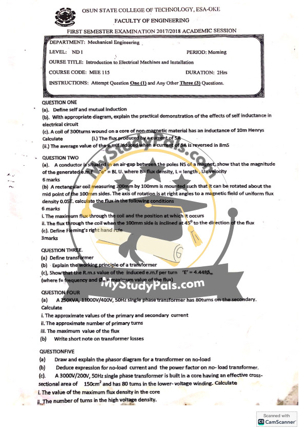
ANWSER
Question 1:
(a) Self-induction: Self-induction is the phenomenon where a change in current in a coil induces an electromotive force (e.m.f) in the same coil due to the changing magnetic field.
Mutual Induction: Mutual induction occurs when a changing current in one coil induces an e.m.f in a neighboring coil due to the magnetic field interaction between them.
(b) Effects of Self-Inductance in Electrical Circuits:
- In AC circuits, self-inductance opposes the change in current, leading to energy storage in the magnetic field.
- In DC circuits, self-inductance affects the switching of currents, leading to voltage spikes.
- Practical Demonstration: A coil connected to a DC source with a switch and a bulb. When the switch is turned off, a high voltage spike may cause a spark across the switch due to self-induction.
(c) Given:
Inductance L=10HL = 10H,
Turns N=300N = 300,
Current I=5AI = 5A
(i) Flux produced by a current of 5A
Flux linkage λ=L×I\lambda = L \times I
λ=10H×5A=50\lambda = 10H \times 5A = 50 Weber-turns.
Since λ=Nϕ\lambda = N\phi,
ϕ=λN=50300=0.1667\phi = \frac{\lambda}{N} = \frac{50}{300} = 0.1667 Weber
(ii) Average value of induced e.m.f when the current reverses in 8ms
Using the formula:
e=LdIdte = L \frac{dI}{dt}
Here, dI=10AdI = 10A (as the current reverses from +5A to -5A), and dt=8ms=0.008sdt = 8ms = 0.008s
e=10×100.008=12,500Ve = 10 \times \frac{10}{0.008} = 12,500V
Question 2:
(a) Proof of e.m.f formula e=BLUe = B L U
From Faraday’s Law, induced e.m.f is:
e=dΦdte = \frac{d\Phi}{dt}
Magnetic flux Φ=B×A\Phi = B \times A, where A=L×U×dtA = L \times U \times dt,
e=B×L×Ue = B \times L \times U
(b) Flux calculations for rectangular coil
Given:
- 200mm×100mm200mm \times 100mm coil
- Rotates about midpoint of 100mm side
- Magnetic field B=0.05TB = 0.05T
(i) Maximum flux
Φmax=B×A=0.05×(0.2×0.1)\Phi_{\max} = B \times A = 0.05 \times (0.2 \times 0.1)
Φmax=0.001\Phi_{\max} = 0.001 Weber
(ii) Flux when inclined at 45°
Φ=Φmax×cos45∘\Phi = \Phi_{\max} \times \cos 45^\circ
Φ=0.001×0.707=0.000707\Phi = 0.001 \times 0.707 = 0.000707 Weber
(c) Fleming’s Right-Hand Rule
It determines the direction of induced current when a conductor moves in a magnetic field.
- Thumb = Motion
- Forefinger = Field
- Middle finger = Induced current
Question 3:
(a) Transformer Definition:
A transformer is a static electrical device that transfers electrical energy between two or more circuits through electromagnetic induction.
(b) Working Principle:
A transformer operates on the principle of mutual induction. When an alternating current passes through the primary coil, it produces a changing magnetic field, which induces an e.m.f in the secondary coil.
(c) RMS value of induced e.m.f per turn:
The formula is:
E=4.44fΦmE = 4.44 f \Phi_m
where:
ff = Frequency,
Φm\Phi_m = Maximum magnetic flux
Question 4:
(a) Given a 250kVA, 11000V/400V, 50Hz transformer with 80 turns on the secondary, calculate:
(i) Approximate primary and secondary current
Using: S=V×IS = V \times I
Primary current:
Ip=SVp=250,00011,000=22.73AI_p = \frac{S}{V_p} = \frac{250,000}{11,000} = 22.73 A
Secondary current:
Is=SVs=250,000400=625AI_s = \frac{S}{V_s} = \frac{250,000}{400} = 625 A
(ii) Number of primary turns
Using: NpNs=VpVs\frac{N_p}{N_s} = \frac{V_p}{V_s}
Np=11,000400×80=2,200 turnsN_p = \frac{11,000}{400} \times 80 = 2,200 \text{ turns}
(iii) Maximum flux
Using E=4.44fΦmNpE = 4.44 f \Phi_m N_p
Rearrange for Φm\Phi_m:
Φm=E4.44fNp=11,0004.44×50×2,200\Phi_m = \frac{E}{4.44 f N_p} = \frac{11,000}{4.44 \times 50 \times 2,200}
Φm=0.0227 Weber\Phi_m = 0.0227 \text{ Weber}
(b) Transformer Losses:
- Copper loss: Due to winding resistance
- Iron loss: Hysteresis and eddy current losses
- Stray losses: Leakage flux effects
- Dielectric loss: Insulation failure
Question 5:
(a) Phasor Diagram of Transformer on No-load:
- Voltage and flux are in phase.
- Magnetizing current lags behind the applied voltage by 90°.
- Core loss component is in phase with voltage.
(b) No-load current and Power Factor:
- No-load current consists of magnetizing and loss components.
- Power factor is low, mainly due to magnetizing current.
(c) Given 3000V/200V, 50Hz transformer:
- Effective cross-sectional area: 150cm2=0.015m2150 cm^2 = 0.015m^2
- Low-voltage winding turns: 8080
(i) Maximum Flux Density BmaxB_{\max}:
Bmax=V4.44fANB_{\max} = \frac{V}{4.44 f A N}
Bmax=30004.44×50×0.015×NpB_{\max} = \frac{3000}{4.44 \times 50 \times 0.015 \times N_p}
For primary turns:
Np=3000200×80=1,200N_p = \frac{3000}{200} \times 80 = 1,200
Now,
Bmax=30004.44×50×0.015×1200B_{\max} = \frac{3000}{4.44 \times 50 \times 0.015 \times 1200}
Bmax=0.075 TB_{\max} = 0.075 \text{ T}
(ii) Number of turns in high voltage winding:
Using NpNs=VpVs\frac{N_p}{N_s} = \frac{V_p}{V_s},
Np=3000200×80=1200N_p = \frac{3000}{200} \times 80 = 1200 turns.


