ANWSER
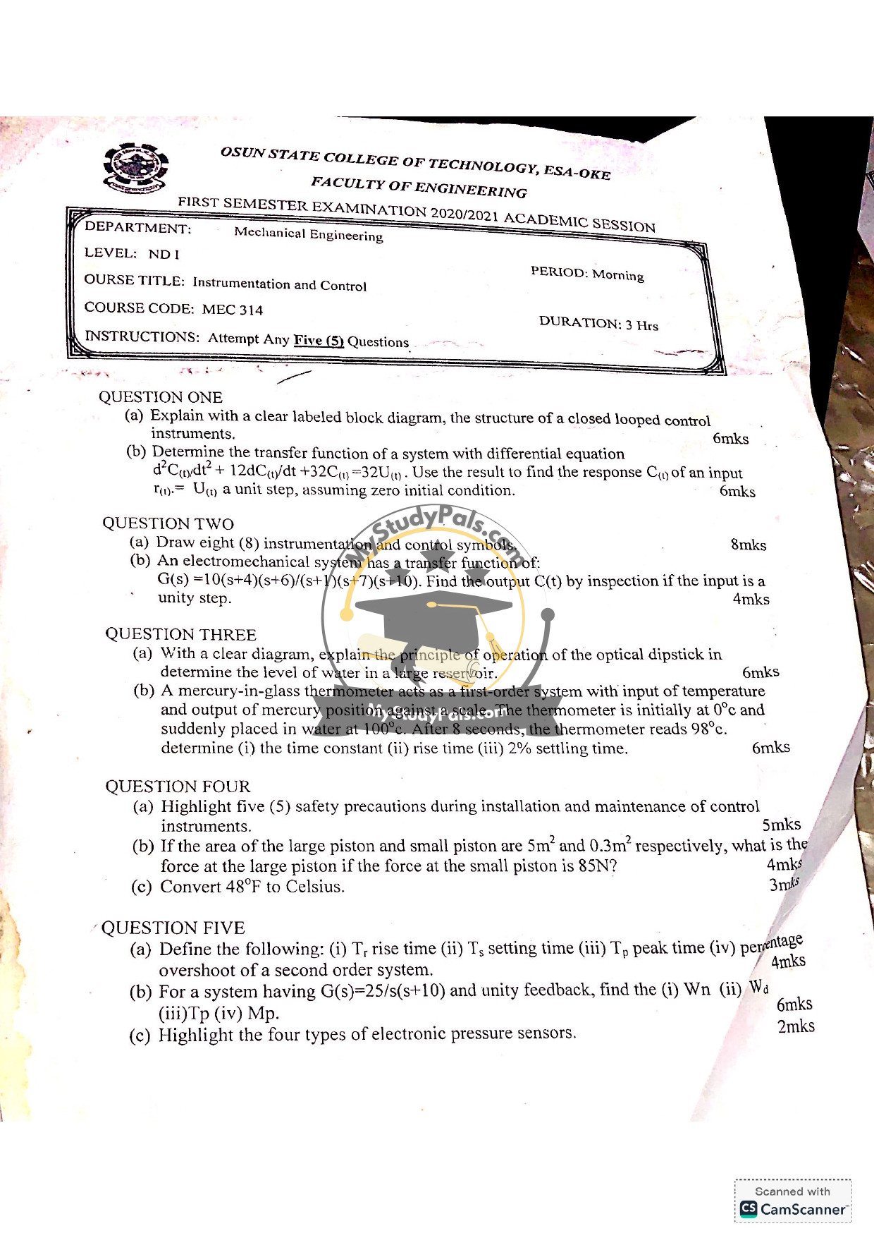
Question 1:
(a)
A closed-loop control system consists of the following components:
1. Reference Input (Set Point): The desired value.
2. Controller: Compares the set point with feedback and generates a control signal.
3. Actuator: Converts the control signal into a physical action.
4. Process/Plant: The system being controlled.
5. Sensor/Transducer: Measures the output and provides feedback.
6. Feedback Loop: Returns the measured output to the comparator.
Block Diagram:
“`
Reference Input → [Comparator] → [Controller] → [Actuator] → [Process] → Output
↑ ↓
└──────[Sensor] ←───────────────┘
“`
(b)
Given the differential equation:
\[ \frac{d^2C(t)}{dt^2} + 12\frac{dC(t)}{dt} + 32C(t) = 32U(t) \]
Step 1: Take the Laplace transform (assuming zero initial conditions):
\[ s^2C(s) + 12sC(s) + 32C(s) = 32U(s) \]
Step 2: Factor out \( C(s) \):
\[ C(s)(s^2 + 12s + 32) = 32U(s) \]
Step 3: Solve for the transfer function \( \frac{C(s)}{U(s)} \):
\[ \frac{C(s)}{U(s)} = \frac{32}{s^2 + 12s + 32} \]
Step 4: For a unit step input \( U(s) = \frac{1}{s} \), the output is:
\[ C(s) = \frac{32}{s(s^2 + 12s + 32)} \]
Step 5: Perform partial fraction decomposition and inverse Laplace transform to find \( C(t) \).
—
Question 2:
(a)
Eight instrumentation and control symbols:
1. Flow Sensor
2. Pressure Transmitter
3. Temperature Sensor
4. Control Valve
5. PLC (Programmable Logic Controller)
6. Motor
7. Pump
8. Solenoid Valve
(b)
Given transfer function:
\[ G(s) = \frac{10(s+4)(s+6)}{(s+1)(s+7)(s+10)} \]
For a unity step input \( R(s) = \frac{1}{s} \), the output \( C(s) \) is:
\[ C(s) = G(s) \cdot R(s) = \frac{10(s+4)(s+6)}{s(s+1)(s+7)(s+10)} \]
Perform partial fraction decomposition and inverse Laplace transform to find \( C(t) \).
—
Question 3:
(a)
Optical Dipstick Principle:
An optical dipstick uses light reflection to measure liquid levels. A light source and detector are placed at the dipstick’s tip. When the tip contacts the liquid, light reflects differently, indicating the level.
(b)
Given:
– Initial temperature: 0°C
– Final temperature: 100°C
– Reading after 8 seconds: 98°C
For a first-order system:
\[ T(t) = T_f (1 – e^{-t/\tau}) \]
At \( t = 8 \), \( T(8) = 98 \):
\[ 98 = 100(1 – e^{-8/\tau}) \]
Solve for \( \tau \):
\[ \tau \approx 1.96 \text{ seconds} \]
(i) Time Constant: \( \tau = 1.96 \text{ s} \)
(ii) Rise Time: \( T_r \approx 2.2\tau = 4.31 \text{ s} \)
(iii) 2% Settling Time: \( T_s \approx 4\tau = 7.84 \text{ s} \)
—
Question 4:
(a)
Five safety precautions:
1. De-energize equipment before maintenance.
2. Use proper PPE (Personal Protective Equipment).
3. Follow lockout/tagout procedures.
4. Ensure proper grounding of instruments.
5. Regularly calibrate and inspect instruments.
(b)
Given:
– \( A_1 = 0.3 \text{ m}^2 \), \( F_1 = 85 \text{ N} \)
– \( A_2 = 5 \text{ m}^2 \), \( F_2 = ? \)
Using Pascal’s principle:
\[ \frac{F_1}{A_1} = \frac{F_2}{A_2} \]
\[ F_2 = F_1 \cdot \frac{A_2}{A_1} = 85 \cdot \frac{5}{0.3} \approx 1416.67 \text{ N} \]
(c)
Convert 48°F to Celsius:
\[ °C = \frac{5}{9}(48 – 32) \approx 8.89°C \]
—
Question 5:
(a)
Definitions:
– Rise Time (\( T_r \)): Time to rise from 10% to 90% of final value.
– Settling Time (\( T_s \)): Time to reach and stay within a tolerance band (e.g., 2%).
– Peak Time (\( T_p \)): Time to reach the first peak.
– Percentage Overshoot: Maximum peak value minus final value, expressed as a percentage of final value.
(b)
Given \( G(s) = \frac{25}{s(s+10)} \), with unity feedback:
– Closed-loop transfer function: \( \frac{25}{s^2 + 10s + 25} \)
– Compare to standard form \( \frac{\omega_n^2}{s^2 + 2\zeta\omega_n s + \omega_n^2} \):
– \( \omega_n = 5 \text{ rad/s} \)
– \( \zeta = 1 \) (Critically damped)
– (i) \( \omega_n = 5 \text{ rad/s} \)
(ii) \( \omega_d = \omega_n \sqrt{1 – \zeta^2} = 0 \) (No oscillation)
(iii) \( T_p = \text{Not applicable} \) (No overshoot)
(iv) \( M_p = 0\% \) (No overshoot)
(c)
Four types of electronic pressure sensors:
1. Strain gauge
2. Capacitive
3. Piezoelectric
4. Optical
—
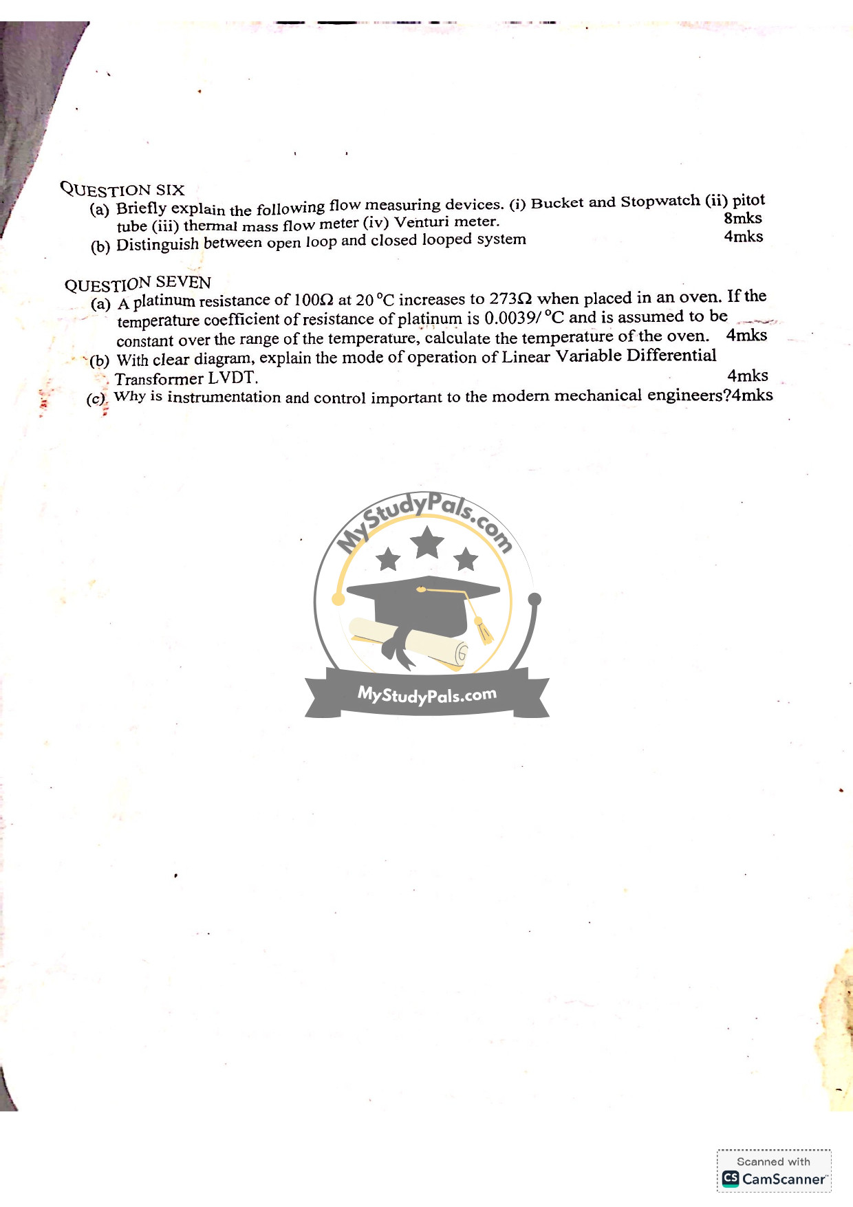
Question 6:
(a)
Flow measuring devices:
1. Bucket and Stopwatch: Measures flow by collecting fluid in a bucket for a timed interval.
2. Pitot Tube: Measures fluid velocity by comparing stagnation and static pressure.
3. Thermal Mass Flow Meter: Measures flow based on heat transfer from a heated element.
4. Venturi Meter: Measures flow by pressure drop across a constricted section.
(b)
Open Loop: No feedback; output is not compared to input.
Closed Loop: Uses feedback to adjust output based on input comparison.
—
Question 7:
(a)
Given:
– \( R_0 = 100 \Omega \) at 20°C
– \( R_t = 273 \Omega \) at \( T \)°C
– Temperature coefficient \( \alpha = 0.0039/°C \)
Using:
\[ R_t = R_0 (1 + \alpha (T – T_0)) \]
\[ 273 = 100 (1 + 0.0039(T – 20)) \]
Solve for \( T \):
\[ T \approx 463.59°C \]
(b)
LVDT Operation:
– Consists of a primary coil and two secondary coils.
– A movable core alters the magnetic coupling between coils.
– Displacement changes the voltage difference in secondary coils, indicating position.
(c)
Importance of Instrumentation and Control:
1. Enhances system efficiency and accuracy.
2. Enables automation and remote monitoring.
3. Improves safety and reliability.
4. Facilitates data collection and analysis for optimization.


