ANWSER
—
Question 1:
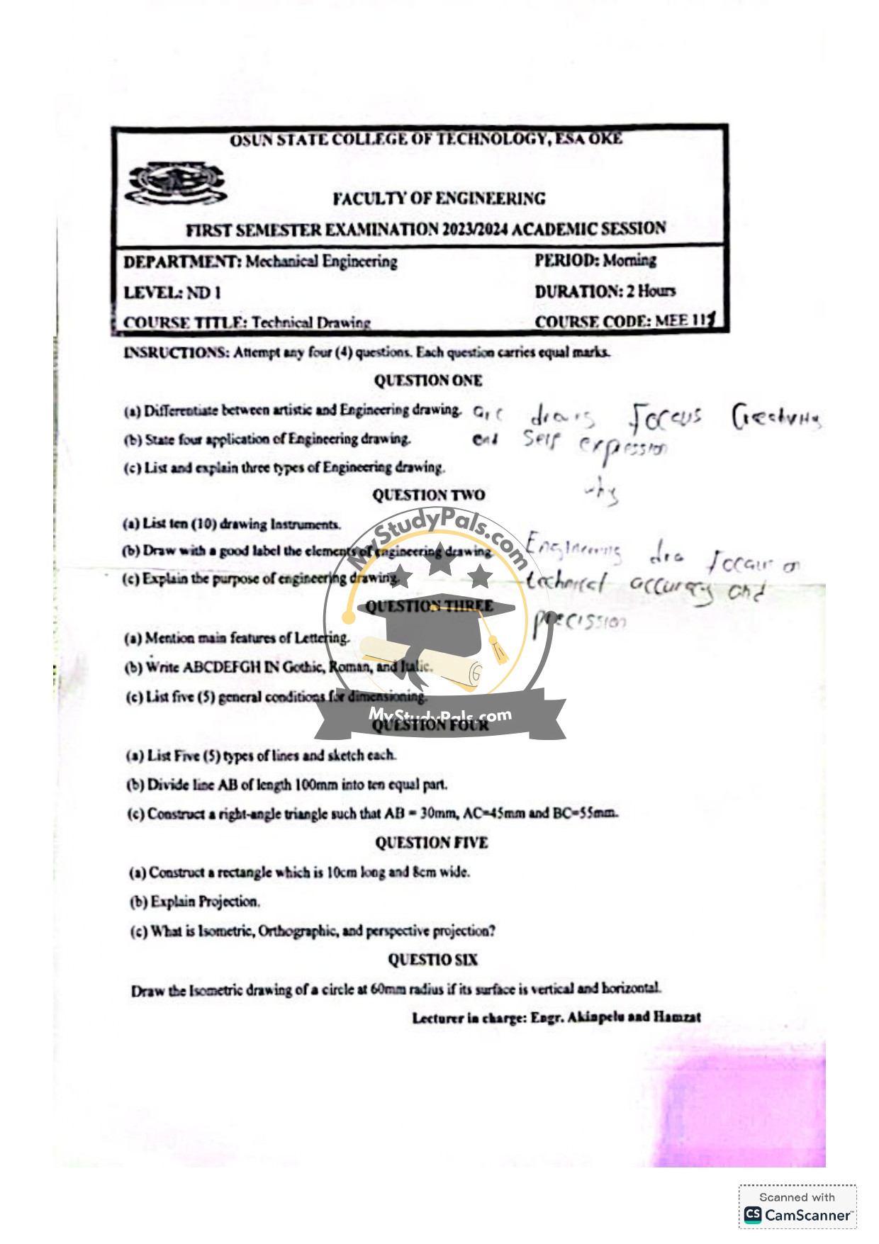
(a) Differentiate between artistic and Engineering drawing.
– Artistic Drawing: Focuses on creativity, aesthetics, and expression. It is subjective and may not follow strict rules or measurements.
– Engineering Drawing: Focuses on precision, accuracy, and technical details. It follows standardized rules and conventions to communicate design and manufacturing information.
(b) State four applications of Engineering drawing.
1. Design and development of machinery and structures.
2. Manufacturing and construction processes.
3. Documentation for patents and legal purposes.
4. Communication between engineers, architects, and technicians.
(c) List and explain three types of Engineering drawing.
1. Orthographic Drawing: Represents a 3D object in 2D views (front, top, side).
2. Isometric Drawing: Shows a 3D object with equal foreshortening on all three axes.
3. Schematic Drawing: Illustrates systems or processes using symbols (e.g., electrical circuits).
—
Question 2:
(a) List ten (10) drawing Instruments.
1. Drawing board
2. T-square
3. Set squares (30°/60° and 45°)
4. Compass
5. Divider
6. Protractor
7. French curves
8. Scale ruler
9. Pencils (H, HB, 2B)
10. Eraser
(b) Draw with a good label the elements of engineering drawing.
*(Note: A sketch would typically include labels for title block, border, drawing area, dimensions, notes, and scale.)*
(c) Explain the purpose of engineering drawing.
Engineering drawings provide a clear, standardized way to communicate design intent, dimensions, materials, and manufacturing instructions to ensure accuracy and consistency in production.
—
Question 3:
(a) Mention main features of Lettering.
1. Legibility
2. Uniformity in size and style
3. Proper spacing between letters and words
4. Consistency in stroke thickness
(b) Write ABCDEFGH in Gothic, Roman, and Italic.
*(Note: This requires handwritten examples. Generally:)*
– Gothic: Block letters, uniform thickness (e.g., A B C).
– Roman: Serif letters with varying thickness (e.g., *A B C*).
– Italic: Slanted letters, often cursive-like (e.g., *A B C*).
(c) List five (5) general conditions for dimensioning.
1. Dimensions should be clear and unambiguous.
2. Avoid duplicate dimensions.
3. Place dimensions outside the object outline where possible.
4. Use consistent units (e.g., mm).
5. Dimensions should not cross extension lines.
—
Question 4:
(a) List Five (5) types of lines and sketch each.
1. Continuous thick line: Visible outlines.
2. Continuous thin line: Dimensions, extensions.
3. Dashed line: Hidden edges.
4. Chain line: Centerlines.
5. Zigzag line: Long breaks.
(b) Divide line AB of length 100mm into ten equal parts.
*(Method: Use a ruler and compass to mark 10mm intervals along AB.)*
(c) Construct a right-angle triangle with AB=30mm, AC=45mm, BC=55mm.
1. Draw AB = 30mm.
2. From A, draw an arc of radius 45mm.
3. From B, draw an arc of radius 55mm.
4. Intersection point is C. Join AC and BC.
—
Question 5:
(a) Construct a rectangle 10cm long and 8cm wide.
1. Draw base line = 10cm.
2. At each end, erect perpendiculars = 8cm.
3. Join the tops to complete the rectangle.
(b) Explain Projection.
Projection is a method to represent a 3D object on a 2D surface by extending points/lines from the object to a projection plane.
(c) What is Isometric, Orthographic, and Perspective projection?
– Isometric: 3D drawing with equal foreshortening on all axes (120° angles).
– Orthographic: 2D views (front, top, side) with no perspective.
– Perspective: 3D drawing with vanishing points for realism.
—
Question 6:
Draw the Isometric drawing of a circle (60mm radius) in vertical and horizontal planes.
*(Note: In isometric, circles appear as ellipses. Use isometric grid or ellipse templates.)*
1. For horizontal plane: Draw ellipse with major axis perpendicular to the vertical isometric axis.
2. For vertical plane: Orient the ellipse based on the chosen isometric axis (left/right).
—


